Last modified: 2023-03-29
General notes

This is how I set-up my Raspberry Pi to be used as external flasher.
There are two ways to flash coreboot into motherboard.
Internal flashing - boot a operating system on the motherboard, install flashrom and flash it via motherboard's internal SPI iterface. This methid is preferable due to simplicity, but not always possible.
External flashing - user external tool to flash the motherboard. If the flash-chip with BIOS is socketed, you can extract it and flash it with programmer. If the flash chip is soldered to the motherboard, you can do in-circuit flashing by connecting to chip's pins.
Gotchas
Create a backup of the original BIOS by reading the SPI flash chip.
The original can be flashed back in case the coreboot fails, but also some useful things might be extracted from it such as vgabios, IntelME, network card driver and so on.
Read out the SPI flash chip multiple times (two or three) and compare their checksums to veryfy that the electrical connection is solid.
If the flashing procedure failed, do not power down the setup! Research about possible solutions.
Always check the your RAM modules are placed into correct slots (look into manual).
Often there are 4 slots (from closest to CPU): A1, A2, B1, B2. Then there are following possible configurations:
- 1 DIMMs:
A2 - 2 DIMMs:
A2B2 - 4 DIMMs: all slots
With stock BIOS / UEFI it might be OK to use slightly different placement, but coreboot will likely end up with RAM INIT FAILURE! and fail to boot.
First boot of coreboot always takes longer - this is mostly because of training memory. Any subsequent boots should be faster.
To get started with new board, keep most settings on default (have as few features as possible to keep it simple). Then if succesful, you can enable more features.
You can use serial port for debugging, if you board has one. Enable debugging with Serial port console output and Show POST codes on the debug console.
Look for existing configuration files in coreboot/configs or in another projects like heads.
SPI flash chip pinout
While the following pinout and voltage is common, it might vary between various manufacturers and chip models! Always check datasheet.
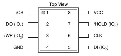
| Pin | Name | Function |
|---|---|---|
| 1 | CS | Chip Select |
| 2 | DO | Data Output |
| 3 | WP | Write Protect |
| 4 | GND | Ground |
| 5 | DI | Data Input |
| 6 | CLK | Serial clock input |
| 7 | HOLD | Hold Input |
| 8 | VCC | Power supply |
Coreboot bassics
Build crossgcc (this will take a while):
make crossgcc CPUS=4
Configure the coreboot build:
make menuconfig
Build coreboot:
make
Serial
Open serial with:
screen /dev/ttyUSB0 115200
To close it Ctrl+A followed by K.